Tribilogix Corporation Oil and Lube Analysis

Lubrication and oil analysis technology is not new to our industry but you would be surprised by the number of companies that do not perform this vital PdM procedure and/or do not have staff that is educated in what test need to be performed. We selected Tribologik as our provider because they are an ISO 17025:2005 certified laboratory, they offer training classes and other resources.

Have you ever wondered what is involved in a specific coolant, lube or oil analysis test!   Tribologik Laboratories has compiled a document which describes each test, the methodology, what it looks for and many other interesting facts.   Click here to see each test and its supporting information.

Tribologik Corporation has over 30 years of experience in used lubricant condition monitoring and testing. The laboratory performs both general and specific oil tests to monitor the condition of large industrial, mining and transport equipment on behalf of global corporations and public utilities in the U.S.A., Canada, Panama, Ecuador, China and Morocco offering reports in five languages: English, Spanish, French, Chinese and Portuguese.

Tribologik laboratories are equipped with the latest technology instruments and are under the guidance of professional scientists with Ph. D. degrees. Furthermore, all technicians are trained and proficient with ISO 17025 :2005 procedures, Best Laboratory Practice and ASTM analysis methods.

Our high level of automation allows quick turnaround time, greater efficiency, interpretation consistency, reliability and quality results. Our laboratories provide oil analysis services on industrial and transport lubricants, fuel, varnish, grease and coolants monitoring the condition of engines, hydraulics, bearings, gearboxes, differentials, transmissions, compressors, pumps and turbines.

Reports are automatically generated using Tribologik Expert Software. Our “Expert System” provides separate diagnostics both on the condition of the oil and of the equipment. It makes maintenance recommendations and the logic behind these recommendations.

If you would like to learn more about Tribologik please click here


Tribologik Laboratories Presents “Oil and Lube Test Explained”

Have you ever wondered what is involved in a specific coolant, lube or oil analysis test!   Tribologik Laboratories has compiled a document which describes each test, the methodology, what it looks for and many other interesting facts.  The different tests are listed at the bottom of the spreadsheet.   Select the test types and see how it can be used in your reliability program.

Click on the “Individual Test Explained” link below to view the document.

Individual Test Explanation

Vibration Transmitters (RMS vs. Peak vs. True Peak)

Vibration transmitters are commonly used in asset reliability programs.  They provide a cost effective means of continuously monitoring the vibration level of the asset.   Vibration transmitters are not machinery protection devices because they do not provide a direct means of shut down.  But they do provide information for Predictive Maintenance and information to plant control systems which can shut down the asset upon a high vibration.

Today’s vibration transmitters offer many more monitoring options than the past.  The output of the transmitter can be selected to be RMS, Peak or True Peak and in units of acceleration (g’s) or velocity (IPS). Most 4-20 mA sensor manufactures, including Wilcoxon offer many different types of sensor ranges and measurement calculations.

How do vibration transmitters calculate these measurement values?

Meter circuits (vibration transmitters) use detectors to establish a level for an AC signal.  Average detectors were used in the first simple voltmeters.  To be more representative of the power in the signal, RMS meters were developed. When we lived in the world of analog voltmeters, it was important to know if the meter was average responding or RMS responding and how the meter function was calibrated.

All this ‘knowledge’ is now buried inside digital meters and is rarely talked about.  However, there are some important distinctions that need to be discussed. Cheap RMS meters continue to use average detectors calibrated for RMS circuits. This was fine when meters were limited to measuring AC line voltage because everything in the US was 110 volts/60 Hz.

However, in our world of dynamic waveforms (vibration signals), no longer are we limited to just 60 Hz signals. Vibration signals run the gamut of ~0.5 Hz to 10,000 Hz+. The early RMS detectors were limited in their frequency range to a few hundred Hertz.  Because of their limited frequency range, true RMS detectors with a wider frequency range were developed to accommodate the growing requirement of vibration signal analysis.

With the wider frequency range a new problem developed.  How could a meter that was responsive to 0.5 Hz signals, 2 seconds in length, co-exist with signals of 10,000 Hz, 0.0001 seconds in length?  If the detector followed the 10,000 Hz signal it would be very fast responding but would misrepresent the information from the 0.5 Hz signal. If the meter was slowed down to accurately report the value at 0.5 Hz, whatever was happening at 10,000 Hz would be completely missed. To solve this problem a compromise was reached in engineering circles; signals with wide bandwidths (vibration), would have a 1 second averaging time as it most accurately represents the input signal.

Therefore, the output from a 4-20 mA RMS vibration transmitter represents some level over a fixed time period, usually 1 second. What is the process of RMS, root-mean-square calculations?  In this calculation processes, the raw AC vibration signal is 1) electronically squared, 2) a mean value is established over a time period and 3) the square root of this mean value is extracted. Unlike some processes, such as Fourier transforms which is a block process, the RMS process is continuous, always updating the value as new data is measured.

Bottom line… Changing the time period of the mean calculation from one second to something else will change the 4-20 mA sensor output from RMS, to Peak or to True-Peak.

Now that you know there is a difference in the method the sensor circuit process the signal, you should also know there is a definite difference in their application.  In the vibration field most users are very familiar with ‘peak values’. Peak values are easy to identify if you have a time waveform to view. Since we do not have that luxury in a 4-20 mA sensor, the transmitter output must somehow represent the peak value of the waveform.  In these sensors most often the averaging time, (the mean calculation) of the RMS detector is shortened. This allows the circuit to closely follow the peak value of an incoming waveform.  A reasonable estimate of the averaging time of a peak detector, as used by most brands, would be in the neighborhood of 100 milliseconds. This is a 10 times faster response than the industry standard RMS vibration transmitter.

For ‘normal’ predictive maintenance monitoring against standards such as ISO 10816, the Wilcoxon ‘peak’ 4-20 mA sensor PC421VP-XX is recommended. This is a true RMS responding sensor calibrated for ‘peak’ levels and very effective in overall vibration monitoring.

The Wilcoxon ‘true peak’ detector uses an averaging time of around 1 millisecond. This is one hundred times faster than the typical ‘peak’ detector vibration transmitter.  In short, Wilcoxon ‘true peak’ vibration transmitters are very effective in identifying early stage roller bearing wear or gear mesh problems. Other applications include reciprocating engines and compressor where impacts are continually present.  The Wilcoxon True Peak vibration sensor is PC421ATP-XX.

Next time you consider installing vibration sensors, remember there is a difference in their design, their purpose and the company that builds them.  Wilcoxon offers superior products, superior product application support and a Life Time Warranty.


Operating Deflection Shape, ODS

A Study of a Bad Foundation
By Allen Plymon

Due to the recent upturn in sales, a wire manufacturing facility needed to increase its production of metal cased conductors. In order to increase the production, the operating speed of the metal forming machines needed to be increased from 900 RPM to 1,200 RPM. However, when operated at 1,200 RPM, the forming machines experienced abnormal vibration. Vibration analysis was performed and levels approaching 1 in/sec 0-PK were recorded at the new fundamental (operating) frequency of the machine, 1200 RPM (20 Hz).  These elevated levels are generally due to either mass unbalance or the unit operating at or near a natural frequency.

The easy solution to mass unbalance correction was to attempt to balance the unit in place. These efforts were successful at the original operating speed of 900 RPM; however, at 1,200 RPM, the vibration levels would return to unacceptable levels – thus eliminating mass unbalance as the root cause. The plant vibration group elected to utilize Operating Deflection Shape analysis of the metal forming machines.

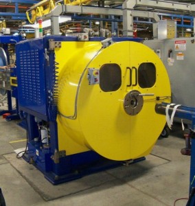
The following image is a photograph of the unit:

Operating Deflection Shape (ODS) is measured with a machine functioning under its normal operational condition.  This type of analysis measures the machine’s response at a specific time or frequency.  Both amplitude and phase information are collected at various locations on the structure and utilizing a special software program, the vibrating “shape” or response of the machine can be animated.  These animations reveal “how” the machine is moving during normal operation.  Note that this is not necessarily a resonant response of the machine, but its operational response.  The forces within the machine are responsible for the motion, or shape of motion measured with this analytical tool.  For example, the unbalance response of any rotating system will produce a response or driving force at 1x RPM.  Misalignment and looseness generally produce synchronous multiples of running speed (2x RPM, 3x RPM…).  Machine information such as operating speed(s), belt and sheave information, blade, vane or gear tooth counts and past structural modifications to the original design are all important for precise diagnoses.

The data collection points and directions are defined based on experience with machinery and how beam, plate and shell structures will bend, twist and deform under vibration forces.  The main concern is collecting enough measurement points to accurately “visualize” the motion.  Another concern is properly measuring across bolted interfaces such that relative motion of the joints, if present can be seen.

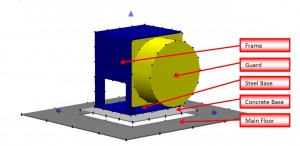
Based on these concepts, the following model was constructed where acquired data is assigned and eventually animated:


Just under 200 points were acquired in order to provide the required resolution of the ODS animation.  Data was collected in the X, Y and Z planes on Channel 1 (reference point) and Channels 2, 3 and 4 at each of the remaining 199 points in the model.  The data was acquired and then stored in the analysis software on the PC.  This information was processed through an extensive matrix where orientation polarity was established consistent with field measurements.  Frequency Response Function (FRF) data was calculated and is defined as the measure of magnitude and phase of the output (Channels 2,3 and 4) as a function of frequency in comparison with the input (Channel 1-Reference).

Finally, this FRF matrix is imported into the animation software and points matched for animation.  With the resulting animation, a thorough study can be performed of the movement of the machine.

To summarize what was expected to be seen, is the frame flexing, which would point to a possible structural resonance and the need to shut down the machine and perform additional impact testing for further analysis.  Some engineering work had already been performed on how to modify the frame structure, based on this belief.

The following movie file links represent multiple views of the machines’ Operation Deflection Shape while operating at 1,000 RPM with a full coil installed.  Please note that the extended dark gray region surrounding the structure represents the main production floor and the rectangular center portion (lighter gray) is where the poured concrete base is inserted.  In addition, the yellow coil guard (entry) is also provided to orient the view of the machine.

3D2 View

There are definitely areas of interest based upon the resultant animations.  These are as follows:

  1. The most pronounced movement is found to be the poured concrete base on which the Machine is mounted relative to the main floor.  As a result, the Machine itself is moving excessively due to its mounting onto this concrete base.
  2. The movement is primarily radial and moves similar to a cantilever with motion at its lowest at the bottom of the machine and levels increasing to the maximum deflection toward the top of the machine.
  3. Motion indicates either a poor attachment of the inertia base or an inadequate sized inertia base for the machine.
  4. The main floor exhibits very low vibration relative to the excessive movement of the machine and machine base.
  5. The frame, bottom machine mounting plate, and inertia base connections as a unit is all in phase and reveal no disconnects or appreciable changes in amplitudes.  This verifies no issues related to the base integrity or soft foot condition.

Further testing revealed a natural frequency at 1,200 CPM (desired operating speed) and that the structural steel was not the source of the elevated vibration.   The concrete pad on which the unit is mounted was rocking on the soil beneath, indicating poor soil compaction.  Upon reviewing the base schematic, it was determined to be insufficient to properly support the forces present on the machine.

Thanks to Operating Deflection Shape analysis capabilities, the solution to the problem was very evident.


Three Advanced Machinery Analysis Test

Operating Deflection Shape (ODS), Bump Tests and Modal Analysis are three tools at the disposal of Plant Engineering and Predictive Maintenance Teams. Each test has its unique purpose and benefit. I have found that many of our customers are unaware of the three tests and/or are confused by their application and purpose.

Let’s start by defining each test…

Bump Test… also known as an impact test, a structure or object is struck with an excitation force such as a soft faced hammer, while measuring the vibration response. When properly excited, the object will respond to the excitation and vibrate at one or more natural frequencies.

Operating Deflection Shape… is an analytical tool where amplitude and phase measurements are collected, normalized and plotted to obtain a visual of how each point “moves” relative to the others. In some cases, software is available to display the movement in an animation format that enhances the analytical process.

Modal… an object is excited with an external force such as a calibrated force hammer or shaker, and the response of the object is measured simultaneously via cross-channel measurements. Excited natural frequencies will incur an amplification of the response and utilizing data generated by a transfer function (system output/system input), amplitude and phase measurements can be animated to display the movement of the object at its natural frequency.

Over the next several months, our newsletter and will focus on these three test as we believe their use will improve the reliability of the rotating machinery assets at your plant.

If you would like to learn how to complete ODS studies, please consider attending our next ODS Class . It will be held in Houston, Texas (25-27 September)

Welcome to our Blog Page!

Hello,

The purpose of this blog page is to provide our customers with product news, applications and case studies.   The data posted on this blog is for information only and  is intended for the privite use of The Normandy Group’s customers.   These posting should not be considered an engineering solution but a reference upon which to build.